Signed in as:
filler@godaddy.com
Signed in as:
filler@godaddy.com
We created a compiled high level-language called psC, generating
Hand-Coded Quality VHDL
for parallel and sequential algorithms.
The foundation of the psC language is discussed below.
As emphasized by Bjarne Stroustrup, the most important objective when designing a language for compilation is to:
Map the language features efficiently onto the machine
Therefore, in order to create a true high-level language for efficient compilation, not for synthesis, we need to ensure that all psC language features map easily onto the FPGA machine. The psC language was designed from the ground up for a "parallel and synchronous machine" like the FPGA.
Let's not forget the machine is a logic circuit. As with all other HDLs (hardware description languages) the main abstraction mechanism is the component. The psC language supports components with IO ports, including hierarchical components. The Novakod Studio environment enables both schematic and textual entry for hierarchical components. Here is an example of a simple counter component:
Hierarchical components are essential, but simple components are the heart of the psC language. Again, for efficient compilation, the language component features must map directly onto the FPGA machine. Let's compare the psC component model with an FPGA circuit to better understand how the psC language easily maps onto the FPGA. Here is the model of a psC component and the code for a simple counter component. The psC maps directly onto a logic circuit:
In the above counter component, there are three input ports, one output port and no variables. The CCounter component has three functions:
In this example, each function has a single assignment and is executed when triggered by an event on the input ports. So, for this example, if there is an event on iUp, the function CountUp() is executed and oValue is increased. It’s that simple! We will explain how events are used in the next section. For those who know about digital systems, you can see that the psC component model is a synchronous sequential circuit. Therefore, you understand how easily and efficiently the compiler can map psC code to an FPGA machine.
It is important to notice how the circuit details are hidden. There is no clock to manage, no combinatorial circuit to define, no flip-flop to control, no state machine to control execution ...
You only use abstract high-level concepts like events, functions and assignments.
As with most HDLs, a psC program consists of interconnected components. In a psC program, one output port connects to one or more input ports using a signal, but a signal is more than a logic value; it contains two pieces of information:
Both the event and the value can be assigned independently using our special assignment operator:
In the example below, the process PSource sets a value and sends an event on the output oP for every event received on the input iP. On the next step, the value and the event are received by the PTarget process. The received event triggers the execution of the function TrgtFct(), which, in turn, executes an assignment and sends an event. Discussion of signal mapping on the FPGA will follow.
In a psC program, processes are instances of components and signals perform inter-process communication.
Each process can receive multiple events simultaneously, and therefore may execute multiple threads of instructions.
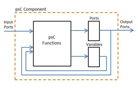
In C++, inter-process communication requires programmed synchronization mechanisms. Since execution of psC is parallel and synchronous, there is no overhead for communication. Effectively, each output port is a shared variable.
Inter-process communications are free.
For large FPGAs, a psC program will have thousands of components and signals, maybe even more. How does this maze of events and functions results in something useful and easy to program? Let's first mention that more than 100 000 lines of psC code have been written for all kinds of applications including signal processing, video drivers, floating point operations... all with hand-coded quality of results. The psC language has been used in teaching digital systems design with only one prerequisite: basic C++ knowledge. Because of its execution model—a psC program only uses events, functions and assignments—it is quite simple to use. Students without prior knowledge of digital systems were able to design a processor.
For now, let's discuss how a psC program executes. Assuming you have a basic understanding of components and signals, here are the execution rules for a complex program that define the parallel and synchronous paradigm.
At each step (clock cycle):
As we now understand, a psC program consists of interconnected components and execution is controlled by events. The last question is:
How does the compiler efficiently manage the events?
As shown below, since a signal contains two pieces of information, additional memory is required for the event. For example, implementation of an integer output port will require 33 bits. When executed, a function might perform a change of value or send events. The compiler will insert two control blocks, one for the assignment and one for the next event. If the assignment symbol contains "=" the assignment control block will send an enable signal to the port or variable being assigned. If the assignment symbol contains ":" the next event control block will set the event latch for one clock cycle.
This overhead is small compared to user-defined execution control based on the clock.
Because of the compiler mapping efficiency, you get Hand-coded quality generated VHDL from high-level psC.